Module 8—Mechanical Waves
 Try This
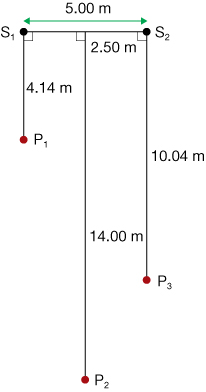
TR 2. Two speakers (S1 and S2) are separated by 5.00 m and emit sound waves in all directions with f = 440 Hz. Three people (P1, P2, and P3) are located at different distances from the speakers, as shown.
- Using the universal wave equation (v = fλ), determine the wavelength emitted by the speakers when the speed of sound is 345 m/s.
- Complete the following table. L1 and L2 represent the path's length from S1 and S2 to the person, respectively. They must be calculated using trigonometry and the data in the figure.
|
To P1 (m) |
To P2 (m) |
To P3 (m) |
L1 (m) |
|
|
|
L2 (m) |
|
|
|
ΔL (m) |
|
|
|
|
|
|
|
Type of Interference |
|
|
|
- What is the pattern between
 and constructive interference?
- What is the pattern between and destructive interference?
- Do the three people all hear the same thing? Why or why not?
For constructive interference to occur, the waves must arrive in phase—the path difference must be a whole number of wave lengths. Expressed mathematically, it is
![]()
For destructive interference, the waves must be out of phase—the path difference is offset by half a wave length. Expressed mathematically, it is
![]()
ΔL is path difference, λ is the wavelength, and n is number of waves.
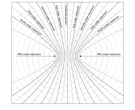
Antinodal and Nodal Lines
In the previous section, you discovered the relationship between path difference and interference. Interference patterns can be quite complex, but they really just consist of regions of constructive and destructive interference. As such, interference patterns form lines.
antinodal line: areas of full constructive interference
nodal line: areas of full destructive interference
Antinodal lines are lines that depict regions of full constructive interference (alternating bright and dark regions on the simulation).
Nodal lines refer to regions where the interference is destructive (grey regions on the simulation).
 Self-Check
SC 5. On the following diagrams, sketch the nodal lines on Figure A and the antinodal lines on Figure B. If you need some help, use the Interference and Huygens’ Principle applet. Set up a similar series of wave sources and, using the path difference option, determine the type of interference.
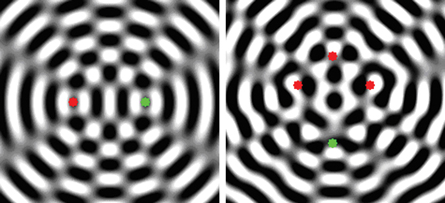
Figure A Figure B
Self-Check Answers
SC 5.

Figure A: nodal lines Figure B: antinodal lines
 Module 8: Lesson 5 Assignment
Remember to submit the answer to TR 3 to your teacher as part of your Module 8: Lesson 5 Assignment.
Try This
TR 3. Imagine that the images in SC 4 depict the surface of a pond. Describe the motion of a water beetle on the surface of the water when it is located at each of the following locations:
- along a nodal line
- along an antinodal line
Interference patterns can be mesmerizing and hypnotic! Spend some time playing with the simulation, and come up with a variety of different patterns.
 Read
Read
Read “An Interference Pattern from Two In-phase Point Sources” on pages 425 to 427 of your textbook.
Self-Check
SC 6. Complete question 8 of “8.3 Check and Reflect” on page 428 of your textbook.
Self-Check Answers
SC 6. There are five minima on each side of the central maximum because a minimum occurs whenever the difference in path length is equal to half an odd number times the wavelength. Thus, a minimum occurs at path length differences of 0.5 λ, 1.5 λ, 2.5 λ, 3.5 λ, and 4.5 λ. Five is the maximum number because the sources are separated by five wavelengths.