Module 5—Circular Motion
 Explore
Using vector diagrams and Newton’s second law, vertical circular motion can be understood in terms of the acceleration acting on an object or rider that moves along a vertically circular path. For simplicity, a simulation will be used in this lesson to produce free-body diagrams for an object attached to a massless, rigid rod travelling in a vertical, circular path. Then, using the free-body diagrams, you will derive equations describing the inward force and tension at the top of the circle, at the bottom of the circle, and at any other position along the circle. From this analysis, you will be able to determine the acceleration acting on an object or rider at any point in the vertical circle.
Visualizing Circular Motion: Vector Diagrams
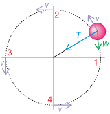
Imagine that a ball is being twirled on a rigid, massless rod in a vertical plane (as shown in the vertical plane on the right). A simulation will be used to illustrate this situation.
You will be using an applet that simulates the motion of a mass on a rod that is moving along a vertical circular path. You can use its free-body analysis to explore the equations describing the inward force and tension at any point along the arc.
Start the Circular Motion: Vertical simulation. On the simulation, select “Vertical Mode” (![]() ) and “Vectors” (
) and “Vectors” (![]() ). Next, use the “Enter a slider value” button (
). Next, use the “Enter a slider value” button (![]() ) below the Initial Velocity slider near the bottom centre of the screen to set the initial velocity to 9.0 m/s. Press “Play.” Observe the motion of the ball, and watch the labels of vectors on the diagram:
) below the Initial Velocity slider near the bottom centre of the screen to set the initial velocity to 9.0 m/s. Press “Play.” Observe the motion of the ball, and watch the labels of vectors on the diagram:
- velocity(v), shown in magenta and always perpendicular to the rod
- weight (W), shown in green and always directed downward, is the gravitational force
- tension (T), shown in blue and always directed inward
 Self-Check
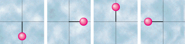
SC 1. Use the simulation. While the ball is revolving, observe the magnitude (size) of the velocity vector and the corresponding speed measurement at the top of the simulation. Label each of the following diagrams with the velocity vector. (Remember to illustrate the relative magnitude of each vector.)
SC 2. Based on your drawing, explain how the velocity is changing in terms of
- direction
- magnitude
Self-Check Answers
SC 1.
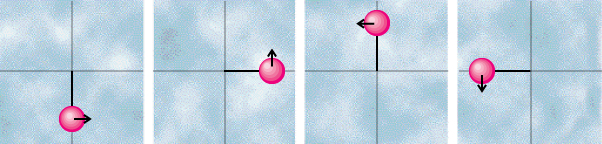
SC 2. The direction is constantly changing but remains perpendicular to the centre of the circle. The magnitude is greatest at the bottom of the circle and least at the top.
 Module 5: Lesson 2 Assignment
Remember to submit the answer to TR 1 to your teacher as part of your Module 5: Lesson 2 Assignment.
 Try This
TR 1. Use the simulation, and observe the tension vector while the ball is rotating.
- Label each of the following diagrams with the tension vector. (Remember to illustrate the relative magnitude of each vector.)
- Identify which diagram has the greatest tension force, which diagram has the least tension force, and which two diagrams have the same magnitude of tension force.
- The tension force is always directed towards the ______ of the circle.
- The tension force is greatest at the ______ of the circle and least at the ______ of the circle.
Self-Check
SC 3. Use the simulation, and observe the weight vector while the ball is rotating.
- Label each of the following diagrams with the weight vector. (Remember to illustrate the relative magnitude of each vector.)
- The weight (gravitational force) is always directed ______.
- The magnitude and direction of the weight vector does not _______.
Self-Check Answers
SC 3.
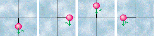
- The weight (gravitational force) is always directed down.
- The magnitude and direction of the weight vector does not change.
Explore the nature and types of forces involved in circular motion by completing this Vertical Circular Motion: Forces tutorial.