Module 3—Effects of Force on Velocity
Working with Forces at an Angle Using Free-Body Diagrams
 Read
Read
All the forces you have considered to this point in the lesson have been parallel to each other or perpendicular. What if the forces occur at an angle to each other? The free-body diagrams are invaluable in sorting things out. Read pages 133 to 135 of your textbook starting at “Adding Non-Collinear Forces.”
 Self-Check
SC 6. In solving “Example 3.3” and “Example 3.4” of your textbook with non-collinear forces, one of the first steps in the solution was to draw a free-body diagram for the object. What was the very next step in both cases?
SC 7. Solve question 2 of "Practice Problems" on page 134 of your textbook.
Self-Check Answers
SC 6. After a free-body diagram for the object was drawn, the next step was to resolve all forces into x and y components.
SC 7.
Given
![]() = 65.0 N [30.0°]
= 65.0 N [30.0°] ![]() = 70.0 N [300°]
= 70.0 N [300°]
Required
the net force on the sled (![]() )
)
Analysis and Solution
Draw a free-body diagram of the situation. An angle of 300° is the same angle as –60°.
Resolve all forces into x and y components. Find the sum of the x and y components separately.
![]()
Vector |
x component |
y component |
|
(65.0 N)(cos 30.0°) |
(65.0 N)(sin 30.0°) |
|
(70.0 N)(cos 60°) |
–(70.0 N)(sin 60°) |
|
91.29 N |
–28.12 N |
Calculate the magnitude of the net force using the theorem of Pythagoras and the direction of the net force using the tangent function.
![]()
The angle measured in polar coordinates is (360° – 17.1°) or 343°.
Paraphrase
The net force on the sled is 95.5 N [343°]
 Module 3: Lesson 4 Assignment
Remember to submit the answer to TR 2 to your teacher as part of your Module 3: Lesson 4 Assignment.
 Try This
TR 2. Solve question 5 of “3.1 Check and Reflect” on page 136 of your textbook.
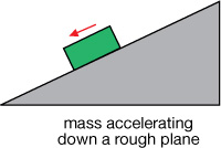
Finding Net Force for Inclined Surfaces

© Larry Buckley/ BigStockPhoto
A roofer is working on an incline.
If you took a summer job in construction that required you to work on a roof, the force of friction would be critical for your safety and productivity. Notice the young worker in the photograph has his foot on a board strapped to the roof for security. Even laying down a tool could be a challenge because it could slide away, which is very inconvenient. The tool may hit someone below, which could cause serious injury.
The forces on inclines also play a role in a host of fun activities such as snowboarding, water sliding, auto racing, skiing, skateboarding, and surfing. You have felt for yourself the dramatic difference in forces on inclines if you have ever ridden a bicycle uphill and then downhill.
In preparation for investigating free-body diagrams on inclines using the Free-Body Drawer simulation, get some background to assist you.
Read
How do you use free-body diagrams to find the net force on an incline? Read “Static Friction on an Incline” on pages 173 to 175 of your textbook. The red and blue broken line vectors are the components of the force of gravity (weight) of the object. The red vector (![]() ) is the component parallel to the slope, and the blue vector is the component perpendicular to the slope (
) is the component parallel to the slope, and the blue vector is the component perpendicular to the slope (![]() ).
).
Self-Check
SC 8. Which component of the weight (![]() ) is equal in magnitude but opposite in direction to the normal force?
) is equal in magnitude but opposite in direction to the normal force?
SC 9. In free-body diagrams of an object on an incline, what is the usual orientation of the reference coordinate axes?
SC 10. If the angle between the slope and the horizontal is 40°, figure out the angle for the following:
- the weight vector (
 ) and the perpendicular component (
 )
)
- the weight vector () and the parallel component (
 )
)
Self-Check Answers
SC 8. The perpendicular component (![]() ) is equal in magnitude but opposite in direction to the normal force.
) is equal in magnitude but opposite in direction to the normal force.
SC 9. In free-body diagrams of an object on an incline, one reference coordinate axis is usually oriented parallel to the slope, with the uphill direction positive (unless the object is accelerating down the slope). The other reference coordinate axis is usually oriented perpendicular to the slope with the upward direction positive.
SC 10.
- The angle between the weight vector () and the perpendicular component () will be 40°.
- The angle between the weight vector () and the parallel component () will be (90° – 40°) or 50°.
Open the Free-Body Drawer simulation, if it is not still open. Select “project” from the drop-down menu titled “Projects” at the top of the applet. Choose the “Image” button (![]() ). Select the lower-left image of an inclined plane, and click OK. You should have the following image on your screen.
). Select the lower-left image of an inclined plane, and click OK. You should have the following image on your screen.
As you did with other images, draw the free-body diagram vectors. Make the weight vector green, the normal vector blue, and the force of friction vector red. Check your work by clicking the “Check” button (![]() ) and selecting “FBD” (
) and selecting “FBD” (![]() ).
).
Self-Check
SC 11. On a copy of your FBDs of the mass accelerating down a rough plane, put in the components of the weight vector that are parallel and perpendicular to the slope using a different shade of green for each.
SC 12. For the object to accelerate down the slope, which component vector must have a greater magnitude than the force of friction? Why?
SC 13. Draw the coordinate axis diagram for the slope situation pictured.
Self-Check Answers
SC 11.
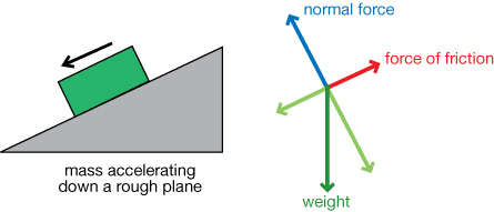
SC 12. For the object to accelerate down the slope, the component of the weight vector parallel to the slope ![]() must have a greater magnitude than the force of friction. According to Newton’s second law, for acceleration to occur, there must be an unbalanced force in the direction of the acceleration. Since the force of friction and
must have a greater magnitude than the force of friction. According to Newton’s second law, for acceleration to occur, there must be an unbalanced force in the direction of the acceleration. Since the force of friction and ![]() are collinear, and the force of friction is opposite to the direction of motion, acceleration occurs down the slope only when
are collinear, and the force of friction is opposite to the direction of motion, acceleration occurs down the slope only when ![]() is greater, so the net force is directed down the slope.
is greater, so the net force is directed down the slope.
SC 13. It also would be perfectly acceptable to have chosen the downhill direction as positive and the uphill direction negative in the diagram below, because the acceleration is downhill.
![]()
Module 3: Lesson 4 Assignment
Remember to submit the answer to TR 3 to your teacher as part of your Module 3: Lesson 4 Assignment.
TR 3. Load the image of the second incline, shown below, using the “Image” button (![]() ).
).
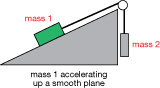
Complete the table by doing the following:
- Identify and list all of the forces in the system. (Assume the “smooth plane” is a frictionless surface.)
- Draw correctly labelled free-body diagrams for both mass 1 and mass 2. Add the relevant components of the weight ( and ).
- On your free-body diagrams, draw convenient coordinate systems and assign vector directions for the situation of both mass 1 and mass 2.
- Derive the relevant net force equations for the FBD for the situations along the slope (mass 1) and also the situation in the vertical direction (mass 2).
Read
Free-body diagrams are essential for solving friction problems involving objects on an incline. To see why, read “Example 3.18” on page 186 and “Example 3.20” on pages 188 and 189 of your textbook. Look for the information you will need to answer the following question.
Self-Check
SC 14. To calculate the force of friction on a slope when the coefficient of friction is given, the normal force is needed.
- How do you calculate the normal force?
- If the sled in “Example 3.20” had a mass of 65 kg, what would the normal force be?
Self-Check Answers
SC 14.
- The normal force and the component of the weight perpendicular to the slope (
 ) are related. They are equal in magnitude but opposite in direction. The formula used is
  .
.
If the sled in “Example 3.20” had a mass of 65 kg, the normal force would be 5.8 × 10² N.