Module 1—Motion
Method 2: Cartesian Method (Polar Positive & Negative)
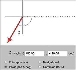
Figure 2
TR 2. On the control panel of the simulation, select the “Polar (pos & neg)” mode without changing any of the settings from TR 1. Verify that the display matches Figure 2.
In this mode, both positive and negative angles are used. Vectors pointing above the horizontal reference line are assigned positive values between 0° and +180°. Vectors pointing below the horizontal reference line are assigned negative values between 0° and –180°.
TR 3. Using the simulation on the “Polar (positive)” mode, set a vector that points into the first quadrant. (Pick a magnitude, and then enter an angle under 90°.) Change the setting to “Polar (pos & neg),” and look at the angle. Repeat this procedure for vectors in the second, third, and fourth quadrants. What is the largest possible angle for the “Polar (pos & neg)” system of coordinates?
 Module 1: Lesson 1 Assignment
Remember to submit the answer to TR 4 to your teacher as part of your Module 1: Lesson 1 Assignment.
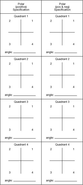
TR 4. Use the applet in the “Polar (positive)” mode and set a vector pointing into the first quadrant. Draw and label the vector magnitude and angle in the following table. Draw the same vector in the “Polar (pos & neg)” row of the table. Predict and label the angle in the “Polar (pos & neg)” mode. Repeat this procedure for vectors in the second, third, and fourth quadrants. Verify your answers using the applet.
Method 3: Navigator Method
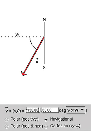
Figure 3
TR 5. On the control panel of the simulation, select the “Polar (positive)” mode in the control panel of the simulation; enter 150 for the magnitude and 240 for the angle. Then select the “Navigational” mode, and choose “S of W” (South of West) from among the eight compass directions in the drop-down menu. Verify that the display matches Figure 3.
“South of West” means that the angle is measured starting from the west direction and then swinging south down towards the position of the vector.
Note: The three compass labels have been added to Figure 3 for your reference; they will not appear on the simulation display.
Module 1: Lesson 1 Assignment
Remember to submit the answer to TR 6 to your teacher as part of your Module 1: Lesson 1 Assignment.
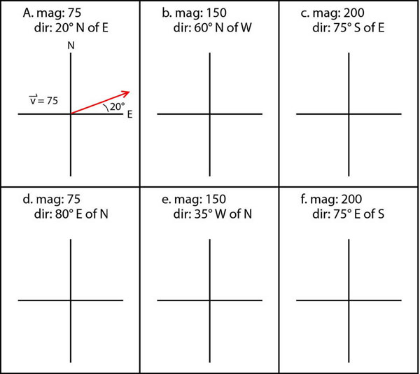
TR 6. Complete the following table by sketching the vectors and labelling the magnitude and direction. (Right-click on the table, and select Print Picture to obtain a paper copy of the table.) The first one has been completed as an example. Use the applet to verify your answers. To position the vector, put your cursor on the very tip of the vector arrow, and when a crosshair appears, click, hold, and drag the tip to wherever you wish.
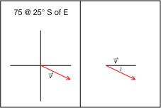
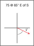
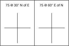
TR 7. Is there more than one way to specify the same navigational direction? Answer this by sketching the following two vectors and labelling the magnitude and direction. Use the applet to verify your answer.
TR 8. What is another way of indicating 75 @ 25°S of E using an angle less than 90°? Draw and label the vector below. Use the applet to verify your answer.